JCAEDE v2n1: Constructing A Simple Interior with 3D Studio
Constructing A Simple Interior with 3D Studio
Joan McLain-Kark
Department of Housing, Interior Design and Resource Management
Virginia Polytechnic Institute and State University
Blacksburg, VA 24061-0424
e-mail: jmkark@vt.edu
Abstract
The tutorial covers the basic steps in making a simple interior with 3D Studio sofware. It takes the user from building the floors, walls, and adding a door opening. Then the user adds materials and mapping coordinates to make a tile floor. Finally lights and cameras are added for a final rendering. This tutorial is best used after the student does a few basics such as Tutorial 1 and 2 from the Autodesk 3D Studio Tutorials (Release 3 & 4). Examples of 6-12 hour projects that were completed after this exercise are presented in the beginning of the tutorial
Constructing A Simple Interior with 3D Studio
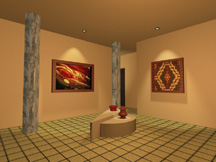
It is easy to construct an interior with 3D Studio (by Autodesk). Below are examples of interiors that were done by using simple shapes doing some basic texturing, lighting, and camera views. Furniture was merged from the World Toolkit provided with the software. Students did this project after completing Tutorials 1-4 and 8-12 of the Autodesk 3D Studio Tutorials and the interiors tutorial that follows. Two more examples are at the end of the article.
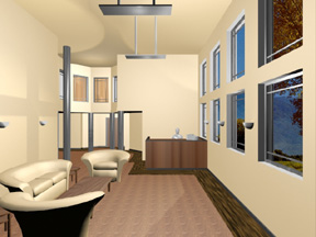
Interior by Jung Park for Advanced CAD, Spring 1997
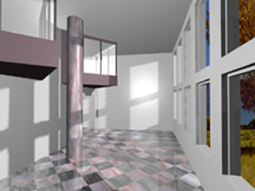
Interior by Chris Turner for Advanced CAD, Spring 1997
You should first set up a drawing (similar to AutoCAD): Click on the following pulldown menus (in bold) to set the units to architectural, snap, grid, and angle snap:
Views
Unit Setup
Architectural
Views
Drawing Aids
Type in 6" for Snap Spacing for X--then just click on Y to have same values for Y and Z.
Type in 1' for Grid Spacing for X--then just click on Y again to have same values for Y and Z.
Type in 0, for Grid Extent Start for X--then click on Y to have same values for Y and Z.
Type in 50' for Grid Extent End for X--then click on Y to have same value for Y and Z (this value may change depending on how large your interior is).
Type in 5 for Angle Snap.
Views
Use Snap (you'll have to do for each viewport)
Use Grid
Use Angle Snap
Zoom Extents Icon --right click
Now you are ready to construct the interior. If you are a CAD user, bear in mind that accuracy is not as important as it is for construction drawings--an inch or two off in interior doesn't really show up. If you are a stickler for accuracy however, then set snap to different settings to get the desired precision.
Click on the right screen menus to make a floor and three walls:
Create
Box
In the Top viewport, make a rectangle about 16'6" wide (X) and 21' long (Y). In Front or Left viewport, make the height about 1'.
Type in FLOOR when prompted for a name.
Zoom Extents Icon --right click
Create
Box
In the Front viewport, make a rectangle starting at the floor surface, making it as wide as the floor and about 8' high. In the Left viewport, make the thickness about 6".
Type in WALLS when prompted for a name. Your wall probably is not in the correct position. To move the wall, click on the following:
Modify
Object
Move
Click on the wall to move to right position.
If you use the tab key, you can make the arrows either go in a vertical or horizontal position if needed. The southwall is the same size as the north wall so you can just copy it by using move again but pressing down the shift key to make a copy:
Modify
Object
Move
In the Left viewport, use the tab key and make the arrow horizontal.
In the Left viewport, press the Shift key and click on the south wall and move to the north.
Type in WALLN when prompted for a name.
Now make the last wall:
Create
Box
In the Left viewport, make a rectangle starting at the floor surface, making it as wide as the floor and about 8' high. In the Front viewport, make the thickness about 4".
Type in WALLW when prompted for a name.
If your walls are too far off (8' thick instead of tall!), you delete by:
Modify
Object
Delete
Click on wall you want to delete.
It is a good idea to save your work. Since you have set some drawing aids--save it as project so your settings will be saved also:
File
Save Project
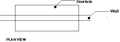
To make windows or doors you will use the boolean feature to cut them out. An alternative method is to draw the wall as an elevation in the 2D Shaper and loft them in the 3D Lofter (but this is my preferred method). You will first make a door hole to use as a tool to cut the hole in the wall. To make the doorhole and have it sit on the floor surface, you can move the construction plane by:
Display
Constr...
Place
In either the Left or Front viewport, click on the top surface of the floor.
Create
Box
In the Top viewport, make a rectangle 3' wide and at least 1' deep. Make sure the length extends over the wall thickness as shown.
Type in DOORHOLE when prompted for a name.
Boolean operations cannot be undone so you will want to save the mesh geometry by clicking on the hold button on right screen menu. Now make the door hole:
HOLD
Create
Object
Boolean
Click on WALLW for the first object.
Click on DOORHOLE for the second object.
Click on OK in Boolean dialogue box because Subtraction is the default.
If you do not see the door opening, you can click on the FETCH button to retrieve the originial mesh geometry and try again. Sometimes, you will get the message that boolean cannot be done. If so, it usually means that another object is overlapping. Rearrange your objects so that only two are touching.
Finish the room by moving the construction plane to the top of the walls (Display-Construction-Place) and make a ceiling about 1' thick.
Now you can assign materials to the walls and floor.
Surface
Material
Choose
Choose BEIGE MATTE.
Click on "by Name" and assign BEIGE MATTE to all walls and ceiling.
Surface
Material
Choose
Choose TILE PINKGRANITE.
Click on the floor to assign TILE PINKGRANITE to the floor.
The material for the floor needs mapping coordinates because it is a bitmap image. You will apply "planar" type of mapping coordinates. However, that is the default so you will not need to change that the type:
Surface
Mapping
Adjust...
Region Fit
In the top viewport, make a rectangle approximaely the size of the floor.
You can see in the Front viewport that the mapping coordinate icon is on the ceiling because the construction plane was on the ceiling. You will move the icon and place on top of the floor (not underneath the surface or it will not work).
Surface
Mapping
Adjust...
Move
In the front viewport, move the icon to the top of the floor.
You will need the adjust the tiling or else you will get just one tile. Because the room is 16' x 20' you will use those numbers to make 1' tiles:
Surface
Mapping
Adjust...
Tile
Enter 16 for X and 20 for Y.
Finally, you must apply the mapping coordinates to the object:
Surface
Mapping
Apply
Object
Click on the floor to assign mapping to floor.
Now you will want to add lights and a camera so that you can render the interior:
Lights
Omni...
Create
In the top viewport, place a light in the center of the room.
Cameras
Create
In the top viewport, place a camera outside the room. Place target inside the room, in the opposite corner (to make a two point perspective). Click on "28mm" lens and then "Create" on Definition dialogue box.
You will replace the User view with the camera view by using pulldown menu:
Views
Viewports
Click on "Camera" button.
Click on lower right viewport (one with U). C should replace the U.
Click on OK.
Your camera view is odd because both the camera and target are on the ceiling (again because the construction plane is on the ceiling). Move the camera:
Cameras
Move
In the Left viewport, move the camera and target to about 5' height or until you have a nice view of the room. Now see your results:
Render
Render View
Click on camera viewport and then OK.
To make mouldings around a door, make a thin box. Do not bother mitering the corners unless you plan to have a close up view of the door. To adjust the height of the moulding or object:
Modify
Axis
Place
Click on the bottom of the moulding or wall.
Modify
Object
2D Scale
Click on the moulding or wall near the top and drag to desired height.
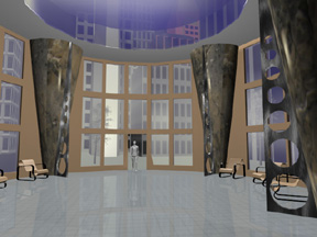
Interior by Eric Sweet for Advanced CAD, Spring 1997
Interior by Wenhui Liu for Advanced CAD, Srping 1997.