JOTS v37n2 - Innovative Rotary Displacer Stirling Engine: Sustainable Power Generation for Private and Fleet Vehicle Applications
Innovative Rotary Displacer Stirling Engine: Sustainable Power Generation for Private and Fleet Vehicle Applications
Phillip R. Foster
Abstract
The Stirling cycle and related terminology is defined. Selected contemporary research involving the cycle in environmentally friendly applications is cited. Three conventional engine configurations that utilize a reciprocating power piston and crank shaft (the Alpha, Beta, and Gamma) are characterized, in terms of minimum number of components, advantages, and disadvantages. A new type of Stirling engine that employs a segmented rotary displacer and other related design improvements is presented along with preliminary findings from engine test runs.
Keywords: Stirling engine, electric power generation, renewable energy
Robert Stirling, in 1816, developed and patented the air engine that bears his name. The steam engines of the early 19th century had a reputation for unreliability, particularly regarding boiler explosion, and the Stirling cycle engine was thought by some as a possible substitute. Fascination regarding the potential for the Stirling cycle can be seen in the prolific development of Stirling cycle engines. Although this cycle provides several distinct advantages over other engine cycles currently in widespread use, there are some noteworthy disadvantages that technology has been hard pressed to eliminate. Thus, most innovation in Stirling engine design has not been adopted. Despite its shortcomings, the Stirling cycle engine is once again under study, but for entirely different reasons.
Worldwide concern over global warming and depletion of nonrenewable energy sources has renewed interest in the Stirling cycle being used for generating green or sustainable energy. Hsu, Lin, and Chiou (2003) reported on what is believed to be the first study of the Stirling cycle, fueled by waste energy, to generate electricity. The heat source was an incinerator. Experimental hardware included a free-piston Stirling engine coupled to a linear alternator. The researchers selected the free-piston Stirling because crank-driven Stirling engines “… presented some challenging design problems, including power modulation, leakage of working fluid, isolation of lubricants, etc.” (Hsu et al., p. 61). Their findings demonstrated the difficulty in simulating actual engine performance, but on a larger scale, these authors pointed the way for other researchers to pursue the topic. In 2008, Snyman, Harms, and Strauss investigated applying the Stirling engine to energy generation through waste heat recovery. Their work focused on the utilization of three design analysis methods for simulating the optimization of a Beta configuration Stirling engine utilizing waste heat. Also included in their research was an experimental setup, using an instrumented Beta Stirling, which was powered by exhaust gases from the combustion of propane. The experimental setup replicated the simulation conditions. The authors’ findings indicated that actual engine performance could be predicted by the simulation analysis. Chang and Ko (2009) also studied waste heat recovery for electricity generation utilizing the Stirling cycle. The renewable heat source used in their research originated from a waste incinerator. Leu (2010) studied the viability of biomass as a heat source for small-scale electrical generation using the Stirling engine. In this application, solid biomass fueled a fixed-bed gasifier with a combustor. Flue gas from the combustor provided the energy input for the Stirling engine-generator set.
The Stirling Cycle and Related Terminology
Stirling Cycle
All modern engines encountered in day-today use operate on a well-known cycle characteristic of their operation. For example, four-stroke reciprocating internal combustion engines utilize spark ignition. These function according to the Otto cycle. Engines that utilize compression ignition adhere to the Diesel cycle. These are mechanical cycles in which the working fluid, a fuel-air mixture, does not undergo a thermodynamic cycle involving cooling to the initial state. They are not reversible. Rather, after combustion imparts work to the mechanism, the remains of the working fluid are expelled from the engine and replaced with fresh mixture. A complete cycle may require one or two 360° revolutions ( Cengel & Boles, 1998 ; Howell & Buckius, 1992 ; Wood, 1991 ).
The Stirling cycle is a reversible thermodynamic cycle consisting of four phases: heat addition (isovolumetric heating), expansion (isothermal expansion), heat rejection (isovolumetric cooling), and compression (isothermal compression). The four phases, which constitute one complete cycle, are completed in a single 360° revolution. A displacer alternately shuttles the working fluid from the cold to the hot workspaces of the engine in synchronization with the power piston. When in the hot workspace, the working fluid is heated, its pressure increases and it expands, thus moving a power piston and doing work. When the displacer shuttles the working fluid into the cold workspace, it is cooled, its pressure is reduced, and the power piston compresses the working fluid back to its original volume ( Beale, 1984 ; Biwa, Tashiro, & Yazaki, 2008 ; Gras, 2011 ; Woodbank Communications, Ltd., 2011 ).
The positive attributes of the cycle have been well known since its inception. They include quiet operation, high thermal efficiency, safe operation, ease of operation, and the ability to function on any form of thermal energy (including both traditional combustion and nonpolluting sources, such as biomass, solar energy, and geothermal energy). Shortcomings of the Stirling cycle have hindered its wider application in competition with steam, electric, and internal combustion. These shortcomings include the complexity of design and a relatively low power output per size and weight ( Beale, 1984 ; Der Minassians & Sanders, 2009 ; Karabulut, Yucesu, & Koca, 2000 ; Snyman et al., 2008 ).
Selected Stirling Engine Terminology
A basic knowledge of selected Stirling engine terminology will help the reader understand the narrative pertaining to contemporary engine configurations. Further, it is essential to an understanding of the major objectives of this article, that is, the discussion of an innovative rotary displacer Stirling engine. The following terms are defined: phase angle, dead space, regenerator, working fluid, workspace, displacer, and volume compression ratio.
Phase angle (a). The displacer piston always moves in advance of the power piston. Both pistons are mechanically connected to a common flywheel and crankshaft. Typically, the phase angle is 90° ( Senft, 2002 ; Snyman et al., 2008 ).
Dead space (dead volume). Conduits, passageways, internal heat exchangers, and similar features for conveying the working fluid that is not directly shuttled by the displacer make up the dead space. Some dead space is inevitable, but it must be minimized because it is detrimental to the indicated work of the cycle ( Senft, 2002 ).
Regenerator. A feature consisting of layers or coils of heat-absorbent material located on the internal surfaces of working fluid conduits or passageways. This feature is used to increase the efficiency of the cycle by (a) accumulating excess heat from the expanding working fluid, which can then be transferred to the fluid during subsequent cycles, and (b) reducing the amount of heat that must be accommodated by the external heat sink through the cold workspace ( Snyman et al., 2008 ).
Working fluid (working gas). The design of Stirling engines is such that the internal spaces contain a gas that is alternately heated and cooled during the cycle but is unable to escape from the mechanism. This gas, referred to as the working fluid or working gas, is commonly air. However, gases with lighter molecular weight (i.e., helium or hydrogen) provide thermodynamic advantages over air. The working fluid is not consumed in the cycle ( Snyman et al., 2008 ).
Workspace. The interior volume of the displacer housing, excluding the displacer itself and any engine dead space, constitutes the workspace. This area contains the bulk of the working fluid and has provisions for the addition and rejection of heat. These provisions subdivide the workspace into the hot workspace and the cold workspace, areas that are thermally insulated from each other.
Displacer. The displacer is a reciprocating piston that moves along the axis of the displacer housing, thus alternately communicating the working fluid to the hot and cold workspaces of the engine ( Beale, 1984 ; Der Minassians & Sanders, 2009 ).
Volume compression ratio. Any given engine has a maximum volume and a minimum volume. The former is the sum of the displacer volume plus the power piston cylinder volume. The latter is the displacer volume alone. The ratio of the maximum engine volume to the minimum engine volume is referred to as the volume compression ratio ( Senft, 2007 ).
Conventional Commercial Stirling Engine Configurations
Three related engine configurations have persisted over the years and these are most commonly used in contemporary commercial applications: the Alpha, the Beta, and the Gamma. All of these configurations utilize the conventional piston, crankshaft, and cylinder arrangement, but two of the three (i.e., Beta and Gamma) use them in conjunction with a uniquely Stirling cycle addition, the displacer. The following sections characterize the three prevalent reciprocating piston-type Stirling cycle engines. Descriptions and figures are generic interpretations of these configurations. No attempt has been made to describe or render the complexities associated with actual working engines.
Characteristics of the Alpha Stirling Engine
The Alpha Stirling engine consists of two power pistons, each with a separate cylinder and connecting rod. One power piston and cylinder represents hot workspace, the other cold workspace. The connecting rods join a common journal on a single flywheel/crankshaft. This arrangement is shown in Figure 1. As the figure depicts, the hot and cold workspaces are physically separated from each other. This feature provides excellent thermal isolation for the two workspaces. The conduit that joins the two workspaces, however, adds to the dead space associated with this design.
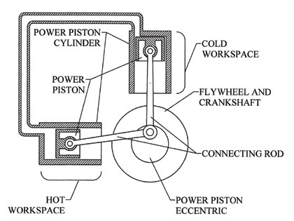
The Alpha then, in its simplest form, utilizes four reciprocating parts and one rotary part. This configuration requires a close tolerance fit between each power piston and its respective cylinder. This is not an issue for those components operating within the cold workspace. The hot workspace piston and cylinder do represent a problem with regard to maintaining a reliable seal in an environment with high heat coupled with sliding friction. Seals on this piston can be subject to early failure due to these operating conditions. Techniques that alleviate piston seal failure may also increase engine dead space. The Alpha is known for its high power-to-volume ratio.
Characteristics of the Beta Stirling Engine
The Beta Stirling engine included design features that eliminated the hot seal failure issues of the Alpha. The engine utilizes a power piston with a connecting rod, similar to the “cold” power piston of the Alpha, but the “hot” power piston is replaced by a displacer with a connecting rod. The displacer represents a major improvement. The power piston and the displacer both share a common cylinder and a common flywheel/crankshaft. This arrangement is shown in Figure 2. Unlike a piston, the displacer does not require a tight tolerance seal along its surfaces. Its function is to simply shuttle working fluid within the hot and cold workspaces. This insulates the power piston from the high temperatures that exist in the hot workspace. Also, dead space is minimal.
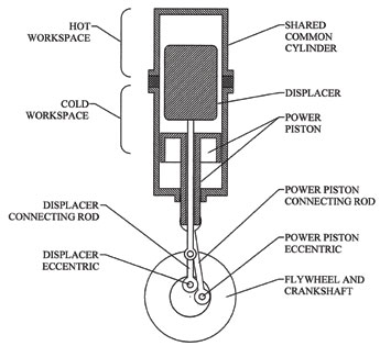
A design in which there is sharing of a common cylinder presents thermal conduction issues not encountered in the Alpha. The junction of Beta hot and cold workspaces must include an additional thermal barrier to reduce conduction and maintain efficiency. The Beta, in its simplest form, consists of four reciprocating parts and one rotary part.
Characteristics of the Gamma Stirling Engine
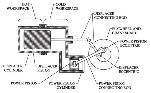
The Gamma Stirling engine is similar to the Beta it that it utilizes the same type of moving parts. It has one major difference. The Gamma power piston does not share a common cylinder with the displacer. Its design employs two distinct cylinders, a feature evident in Figure 3. However, the hot and cold workspaces of the displacer cylinder require the addition of a thermal barrier. Therefore, in its simplest form, the Gamma configuration also consists of four reciprocating parts and one rotary part. The Gamma shares the same advantages as the Beta and also holds the potential for being mechanically simpler. Gammas are particularly suited to multicylinder applications.
In the preceding explanation, the reciprocating and rotating part count was always prefaced by the phrase “in simplest form.” The reality of conventional commercial Stirling design seldom if ever adheres to the simplest form. Contemporary engines display a range of mechanisms, some fairly complex, to change linear motion into rotary.
Summary of Conventional Stirling Configurations
Certain generalizations can be made from the preceding sections. There is a renewed interest in the Stirling cycle for sustainable and/or environmentally friendly electrical generation. Reciprocating piston-type Stirling engines, particularly the Alpha, the Beta, and the Gamma, have been harnessed in these applications and have been reported to be effective. These engine configurations, in their simplest form, utilize four reciprocating parts and one rotary part (per power cylinder). Actual commercial engines are typically more complex (i.e., have more moving parts per power cylinder).
Genesis of the Stirling With Attitude (SWATT) Engine
The author was convinced that the cycle could be effectively achieved with fewer than five moving parts per power cylinder. A reduction in parts, particularly reciprocating parts, would contribute to mechanism longevity while reducing complexity. It was proposed that the cycle be represented by three moving parts, two reciprocating and one rotary. The reciprocating parts included the power piston and connecting rod assembly. The rotary part was the displacer. Integrated into the displacer were the crankshaft/flywheel and a valve mechanism. The crankshaft/flywheel also incorporated provisions for teaming engines to provide greatly simplified, multipower cylinder configurations.
The following parameters were selected as a starting point for initial engine design: liquid cooling, power cylinder bore and stroke = 1.000” X .625” (volume = .491 in3), phase angle 90°, and volume compression ratio 1.244. The power cylinder specifications and the volume compression ratio established the volume of the rotary displacer at 2.009 in3. Materials selected included stainless steel for all major structural components, graphite for the piston, titanium for the connecting rod assembly, and polymer for the rotary displacer. The following sections address design features of major components, specifically, the individual displacer segments, the rotary displacer assembly, the displacer housing, and a rotary valve mechanism.
Individual Displacer Segments
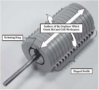
The displacer of the subject engine is not of one-piece construction. Rather, it is made up of 16 polymer segments, 14 of which are virtually identical. Individually balanced, each has a stepped profile along about 180° of the outer circumference (see Figure 4), which is evident along the lower half of the segment in the figure. The same profile is mirror imaged in the internal surfaces of the two-piece stainless steel displacer housing. This design feature increases the surface area of the hot and cold workspace, enabling a more rapid isovolumetric heating (expansion) and cooling (compression) of a larger volume of working fluid. The six holes adjacent to the stepped area balance the segment by removing a mass equivalent to that removed in the creation of the stepped profile.
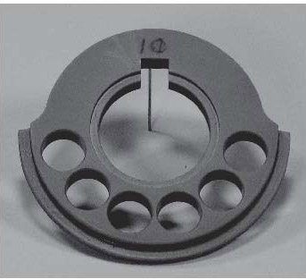
The balancing holes, in the fully assembled displacer, are filled with an expanded foam insert that has a very low mass coupled with a high temperature resistance. If left unfilled, balancing holes would add substantially to the engine’s dead space. The axial hole with keyway locates the segment along the assembled displacer’s long axis while preventing rotation about it. Individual segments are kept in position through two retaining rings, one on either side of each segment. One of these rings is shown in Figure 5.
Using a segmented displacer that had a stepped profile that could enhance the heat transfer area was possible because the displacer was rotary. This permitted the use of one of several relatively new engineered polymers. PolyEtherEtherKetone (PEEK) has mechanical and thermal properties that make it ideal for this application. These include: tensile strength of 16 ksi, compressive strength of 20 ksi, maximum operating temperature of 480°F, thermal conductivity of 1.75 BTU-in./ft.2-hr.-°F, and a coefficient of thermal expansion, 2.6 X 10⁻⁵in./in./°F ( Boedeker Plastics, Inc., 2011 , pp. 2-3). Thus, PEEK is a very good insulator that will neither absorb nor transmit too much thermal energy. It is also strong for a polymer and has a high operating temperature ceiling. Like most polymers, however, it “grows” when heated, and this growth is more than that encountered with most metallics. The type of stainless steel used in the water-cooled displacer housing is AISI 304, which has a much lower coefficient of thermal expansion, 9.6 μ in./in..-°F ( Oberg, Jones, Horton, & Ryffel 2004 , p. 472). Because the displacer segments are individually located along the axis of the housing using retaining rings, their relatively large coefficient of expansion is of consequence for a relatively short lateral dimension, their individual thickness. This expansion is easily accommodated in the sizing of the corresponding workspace for a given segment, even though the stainless “grows” very little by comparison.
The Rotary Displacer Assembly
Adoption of a rotary displacer over a reciprocating one provided two significant advantages. These are reduced cycle power needs and increased design flexibility. Each will be briefly discussed.
Reduced cycle power needs. Reciprocating displacers waste energy. In the 360° rotation representing one complete cycle, the displacer changes direction twice. The displacer is accelerated from rest at 0°. It achieves maximum velocity at 90°, followed by deceleration and rest again at 180°. It is again accelerated achieving maximum velocity at 270°, followed by deceleration as it approaches 360° in its return to starting point. Energy is consumed in both acceleration and deceleration. A rotary displacer, however, never changes direction. Therefore, no engine energy is consumed in the constant acceleration-deceleration associated with the reciprocating arrangement. Further, its mass contributes to that required by the flywheel/crankshaft assembly that is essential to the Stirling cycle.
Increased design flexibility. Reciprocating displacers limit the design options available for optimizing engine operation. This is because minimizing reciprocating mass must take precedence over other factors. Minimizing mass influences material selection, which can result in compromises in thermal and mechanical properties. For example, high stiffness, low weight, low thermal conductivity, and high thermal resistance are also very desirable displacer material characteristics. Unfortunately, it is difficult to identify a cost-effective material selection that offers such diverse characteristics and is, at the same time, low mass. Also affected are the physical design, the axial orientation (vertical vs. horizontal), and displacer surface topology (i.e., its axial cross-section). Surface topology includes design features intended to increase the displacer surface area that is available for heat transfer. Minimal surface area for effective heat transfer has been cited as an issue. Senft (2007, p. 64) wrote “[i]n many real engines the expansion and compression processes for the most part occur in engine spaces that have relatively little heat transfer area.” Mechanism wear must be controlled to maintain an adequate service life. For the same reasons that they waste energy, reciprocating displacers load other components (e.g., bearings and linkages), requiring more robust design of these components.
A rotary displacer, at operational speed, exerts radial and thrust loads only. These are the normal loads placed on bearings, and they do not adversely influence engine design in other areas. A rotary displacer also opens up design options in other ways. Because mass is not an issue, there are novel design opportunities for the displacer. The rotary displacer can be long, can incorporate features for increased surface area, and can still function from ambient to operating temperature within the close confines of the stainless housing.
Figure 5 shows the fully assembled, segmented rotary displacer. The top surface of the displacer creates the hot and cold workspaces of the engine; this is in concert with the hot and cold sections of the displacer housing. The lines appearing along the circumference, indicating the sides of each segment, also represent the physical space between segments. This space allows for the thermal “growth” that is inevitable as the segment warms from close proximity with the hot workspace. Each segment is restricted in its lateral movement associated with this “growth,” by two retaining rings. The maximum extent of this movement, either left or right, always coincides with the width of the corresponding radial groove in the housing.
The Displacer Housing
The displacer housing consists of four major components, all of type 304 stainless steel. The hot and cold workspaces are achieved through two partial cylinders that are joined along their edges to form a complete cylinder. A PEEK seal is located along their linear joints to prevent thermal conduction between the hot and cold workspaces. Their internal configuration, as previously noted, is a mirror image of the rotary displacer. The ends of the housing contain the bearings and provisions for liquid cooling. Additionally, the right-hand end contains features that contribute to the rotary valve mechanism as well as the means for the hot and cold workspaces to communicate with the power piston. The internal ends of the housing are faced with PEEK seals to prevent thermal conduction. Clearances between the rotary displacer and the housing are tight to minimize dead space but sufficient to ensure no contact. Figure 6 shows a single displacer segment in a partial assembly with half of the displacer housing. In this figure, the housing shown is that of the cold workspace (note the coolant manifold connections at the lower left). A single displacer segment is shown here to clarify the internal configuration of the housing, the cold workspace. One segment retaining ring also appears clearly.
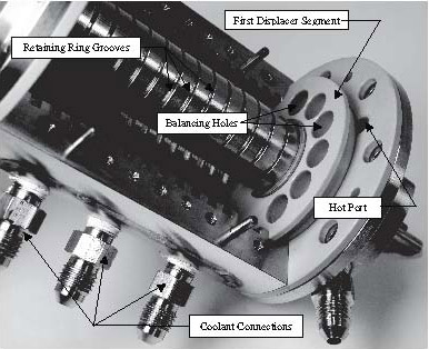
Each of the radial grooves along the inner surface of the cold workspace corresponds to one of the 15 segments not yet in the displacer assembly. The internal configuration of the hot side of the displacer housing is identical to that of the cold side.
Rotary Valve Mechanism
Another design feature that is possible because of the rotary displacer is a rotary valve integral with the first displacer segment and the adjacent portion of the housing. This arrangement does not add additional moving parts, but it effectively directs the working fluid in the following way. The power cylinder has two ports, one in communication with the hot workspace through the hot port (see Figure 6) and one in communication with the cold workspace through the cold port. The cold port is not visible in Figure 6; it is obscured by the segment. Regardless, it is situated 180° from the hot port and lies on the same circular centerline in the side of the displacer housing. These ports are positioned immediately adjacent to the stepped profile groove occupied by the first displacer segment. Recall that the stepped profile of the segments exists for about 180° only (see Figure 3). Hot and cold ports connect to the power cylinder through passageways. The cold port and its passageway represent a heat sink in that they are kept cold by the engine’s liquid cooling system. These areas are also insulated from the hot workspace. The hot port and its passageway represent thermal energy input, being in communication with the hot workspace. When the displacer rotates through its cycle, it alternately blocks and opens the hot and cold ports. During isovolumetric heating (expansion), therefore, the hot working fluid is inhibited from moving through the cold passageway, even though pressure throughout the engine is the same. Similarly, during isovolumetric cooling (compression), the cold working fluid is inhibited from moving through the hot passageway.
Preliminary Findings From Initial Running of SWATT Engine
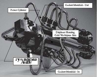
This engine has been under development for approximately 10 years, and much of this time has been spent on design and fabrication. Figure 7 shows the assembled engine from the perspective of the cold workspace. Major subassemblies have been identified.
In order to run the engine, various auxiliary units must be connected. These include a propane gas burner, connections for the liquid cooling, and various instrumentation components. To facilitate collection of engine performance data, a test bed was constructed to hold the engine and auxiliary units. The complete setup has been operable for about two years and has accrued data from about 120 hours of run time. It is instrumented with five externally mounted surface contact type K thermocouple probes. These are located at various positions to collect temperature distribution data. Two probes monitor hot workspace (thermocouple locations 1 and 3), two monitor cold workspace, and one monitors power cylinder temperature, also representing cold workspace (thermocouple locations 2, 4 and 5, respectively). Thermocouple probes are connected to two Fluke 52 II and one Fluke 51 II digital thermometers. This instrumentation displays data that provides the mean hot workspace temperature, the mean cold workspace temperature, and the resulting difference in temperature (ΔT). A noncontact laser photo tachometer, an Extech Model 1PX61, is also mounted on the test bed. This instrument displays the engine’s RPM. Because there is a patent pending on the engine, it is now possible to release some design and performance information.
Although its appearance is radically different from Alpha, Beta, or Gamma Stirling engines, the SWATT engine definitely functions on the Stirling cycle (i.e., the nonconsumed working fluid is alternately heated and cooled but always returns to its initial state with each revolution). Although work on the design parameters it still under way, some unexpected findings regarding one, the phase angle, have come to light. The ideal phase angle was found to be remarkably different from that typically attributed to either Beta or Gamma engines, which operate with a phase angle of approximately 90°. As previously noted, the SWATT engine was initially designed and built with this angle. Initial engine runs, however, indicated ceiling RPM of about 400, which was less than anticipated. By varying the phase angle on the flywheel/crankshaft assembly, it was possible to experimentally determine an ideal phase angle through observation of tachometer readings.
Determination of the Ideal Phase Angle
Eccentrics
The flywheel/crankshaft assembly consists of several components, one of which serves as an eccentric. A cylindrical piece, the eccentric is bored through its longitudinal centerline to connect to the rotary displacer axle. When assembled, only one orientation is possible. A crank pin, which engages the power piston connecting rod, screws into the eccentric. The distance from the eccentric centerline to that of the crank pin establishes the stroke of the engine. The radial displacement of the crank pin, in relation to that of the rotary displacer, establishes the phase angle. Eccentrics were constructed to enable engine operation with phase angles of 75, 80, 85, 115, 120, 125, 130, and 135 degrees. Phase angles on either side of 90° were selected because it was not known whether an ideal angle was less than or greater than 90°.
Engine Performance Log
An engine performance log was developed to standardize data collection during phase angle testing. The log provided for manual recording of the time of an observation, the temperatures at the five thermocouples, and the RPM. Also recorded were the mean hot workspace temperature, the mean cold workspace temperature, and the temperature difference (ΔT) between each. The last three quantities are calculated and recorded post test. A representation of this form is depicted in Table 1. This contains test data for the 90° phase angle.
| Thermocouple Locations (1-5) and Recorded Temperatures (°F) |
Mean Hot:
(T 1 + T 3 ) ÷ 2 (°F) |
Mean Cold:
(T 2 + T 4 + T 5 ) ÷ 3 (°F) |
ΔT:
(Mean Hot – Mean Cold) (°F) |
RPM | |||||
|---|---|---|---|---|---|---|---|---|---|
| Time (h:m) | T 1 | T 2 | T 3 | T 4 | T 5 | ||||
| 4:00 | 77 | 77 | 77 | 77 | 75 | N/A | N/A | N/A | N/A |
| 4:05 | 182 | 80 | 181 | 79 | 76 | 182 | 78 | 104 | 576 |
| 4:07 | 197 | 81 | 185 | 80 | 77 | 191 | 79 | 112 | 577 |
| 4:09 | 197 | 82 | 169 | 81 | 78 | 183 | 80 | 103 | 420 |
| 4:11 | 198 | 82 | 169 | 81 | 79 | 184 | 81 | 103 | 484 |
| 4:13 | 198 | 82 | 168 | 81 | 79 | 183 | 81 | 102 | 428 |
| 4:15 | 190 | 82 | 156 | 81 | 80 | 173 | 81 | 92 | 368 |
| 4:17 | 198 | 82 | 174 | 81 | 80 | 186 | 81 | 105 | 511 |
| 4:19 | 204 | 82 | 179 | 81 | 81 | 192 | 81 | 111 | 407 |
| 4:21 | 198 | 83 | 164 | 81 | 81 | 181 | 82 | 99 | 382 |
| 4:23 | 193 | 83 | 158 | 81 | 81 | 176 | 82 | 94 | 364 |
| 4:25 | 193 | 82 | 159 | 81 | 81 | 176 | 81 | 95 | 392 |
| 4:27 | 194 | 83 | 159 | 81 | 82 | 177 | 82 | 95 | 408 |
| 4:29 | 194 | 82 | 160 | 81 | 82 | 177 | 82 | 95 | 418 |
| 4:31 | 194 | 82 | 161 | 81 | 82 | 178 | 82 | 96 | 426 |
| μ | 195 | 82 | 167 | 81 | 80 | 181 | 81 | 100 | 440 |
Note that the first data row, highlighted in red, shows only time and thermocouple temperatures at the start of the test. Calculation of mean hot and cold workspace temperatures as well as the engine workspace temperature difference (ΔT) are irrelevant at this point. At the bottom of the table, means are provided for temperatures taken at all thermocouple locations, grand means for the hot and cold workspaces, mean temperature difference, and mean RPM for the duration of the test run.
Phase Angle Testing Procedure
Experience running the engine has demonstrated that it needs approximately 20-23 minutes of initial run time to stabilize operation. The term stabilize implies that engine RPM is at or very near maximum, and minimal burner adjustment is necessary to maintain that RPM. This condition is termed steady state, and once achieved, heat input and RPM output remain relatively consistent over the duration of the engine test run.
During the initial 20 minutes of operation, however, constant adjustment of the burner is required. Thus, temperature and RPM data collected during this time display fluctuations that necessarily differ from test run to test run. This is evident in first 11 rows of temperature data for thermocouples monitoring hot workspace (T1 and T3) and the respective RPM figures shown in Table 1. The magnitude of fluctuations is dependent on how aggressively heat is applied. Both excessive heat and insufficient heat are detrimental to maximal RPM. Though high temperatures and RPMs can occur during this time, they do not characterize sustainable operation. These initial temperature and RPM figures are useful, even essential, in stabilizing operation, but that is the extent of their utility. For this reason, it was decided that all test runs in the phase angle study would be 31 minutes in duration with a 23-minute stabilization period, during which collected data would not be utilized to assess the effectiveness of a given angle. Only the last 8 minutes of the test would be used to collect data representing the performance of a given phase angle. The temperature and RPM sampling interval for a complete test run was set at 2 minutes with the exception of the initial reading, which was 5 minutes from the commencement of the test (the engine requires an approximate 3-minute warm up prior to running). All temperatures were recorded in degrees Fahrenheit (°F). Temperatures and RPMs were recorded to the nearest integer and standard rounding practice was used.
Findings: Phase Angles 75°, 80°, and 85°
The 75° phase angle was tested first. It was not possible to start the engine. The same results occurred with the 80° phase angle. At the 85° phase angle, the engine started, but it proved very difficult to stabilize, and the test run was aborted. Therefore, there is no performance data for the first three tests. Lack of run data, however, did provide valuable insight. Because the initial engine configuration successfully employed a 90° phase angle, the difficulties encountered with angles of 75°, 80°, and 85° demonstrated that if there were potential for improved engine RPM performance through phase angle manipulation, that manipulation would involve phase angles of 90° or more.
Findings: Phase Angle 90°
An eccentric having the 90° phase angle suggested by the literature was initially built with the engine. It was effective when the engine was first run, but empirical evidence characterizing the extent of its effectiveness had yet to be collected. Therefore, the fourth phase angle test was based on 90°, and, as previously noted, findings are shown in Table 1. This table, however, can be condensed through the elimination of the run data accrued during the 23-minute stabilization period. This reformatting (see Table 2), which will be used in the discussion of remaining phase angles as well, makes it possible to compile means for temperatures and RPMs that are not influenced by startup fluctuations.
| Thermocouple Locations (1-5) and Recorded Temperatures (°F) |
Mean Hot:
(T 1 + T 3 ) ÷ 2 (°F) |
Mean Cold:
(T 2 + T 4 + T 5 ) ÷ 3 (°F) |
ΔT:
(Mean Hot – Mean Cold) (°F) |
RPM | |||||
|---|---|---|---|---|---|---|---|---|---|
| Time (Minutes into Run) | T 1 | T 2 | T 3 | T 4 | T 5 | ||||
| 25 | 193 | 82 | 159 | 81 | 81 | 176 | 81 | 95 | 392 |
| 27 | 194 | 83 | 159 | 81 | 82 | 177 | 82 | 95 | 408 |
| 29 | 194 | 82 | 160 | 81 | 82 | 177 | 82 | 95 | 418 |
| 31 | 194 | 82 | 161 | 81 | 82 | 178 | 82 | 96 | 426 |
| μ | 194 | 82 | 160 | 81 | 82 | 177 | 82 | 95 | 411 |
Findings indicate a high level of consistency for virtually all temperature readings. The consistency of cold workspace temperatures (taken from locations T2, T4, and T5,) indicates sustainable, effective cooling (grand mean of 82°F). This is characteristic of steady state operation. A similar statement can be said of hot workspace temperatures taken from locations T1 and T3 (grand mean of 177°F). The 90° phase angle also rendered a mean ΔT of 95°F and an RPM of 411.
Findings: Phase Angle 115°
Contained in Table 3 are findings from the 115° phase angle test. Again, temperatures display consistency. Cold workspace temperatures had a grand mean of 80° F, whereas hot workspace temperatures indicate a grand mean of 180°F. This, in conjunction with consistency in RPM, indicates the engine is functioning near steady state. The mean ΔT was 100°F and the mean RPM was 701. The RPM statistic represents a major improvement over that obtained with the 90° angle suggested by the literature.
| Thermocouple Locations (1-5) and Recorded Temperatures (°F) |
Mean Hot:
(T 1 + T 3 ) ÷ 2 (°F) |
Mean Cold:
(T 2 + T 4 + T 5 ) ÷ 3 (°F) |
ΔT:
(Mean Hot – Mean Cold) (°F) |
RPM | |||||
|---|---|---|---|---|---|---|---|---|---|
| Time (Minutes into Run) | T 1 | T 2 | T 3 | T 4 | T 5 | ||||
| 25 | 194 | 80 | 163 | 77 | 81 | 179 | 79 | 100 | 713 |
| 27 | 196 | 80 | 164 | 78 | 82 | 180 | 80 | 100 | 709 |
| 29 | 197 | 80 | 163 | 78 | 82 | 180 | 80 | 100 | 696 |
| 31 | 197 | 80 | 162 | 78 | 82 | 180 | 80 | 100 | 685 |
| μ | 196 | 80 | 163 | 78 | 82 | 180 | 80 | 100 | 701 |
Findings: Phase Angle 120°
Table 4 contains the findings for the 120° phase angle test. Temperatures remained consistent at a given thermocouple over time. Cold workspace temperatures had a grand mean of 82° F, whereas hot workspace temperatures indicate a grand mean of 179°F. These values are similar to those derived from the 115° phase angle data. The ΔT, at 97°F, dropped slightly from that encountered with the previous phase angle, but the average RPM recorded during the test increased to 712.
| Thermocouple Locations (1-5) and Recorded Temperatures (°F) |
Mean Hot:
(T 1 + T 3 ) ÷ 2 (°F) |
Mean Cold:
(T 2 + T 4 + T 5 ) ÷ 3 (°F) |
ΔT:
(Mean Hot – Mean Cold) (°F) |
RPM | |||||
|---|---|---|---|---|---|---|---|---|---|
| Time (Minutes into Run) | T 1 | T 2 | T 3 | T 4 | T 5 | ||||
| 25 | 194 | 82 | 163 | 81 | 82 | 179 | 82 | 97 | 729 |
| 27 | 195 | 83 | 163 | 81 | 82 | 179 | 82 | 97 | 720 |
| 29 | 195 | 83 | 162 | 81 | 82 | 179 | 82 | 97 | 708 |
| 31 | 195 | 83 | 162 | 81 | 82 | 179 | 82 | 97 | 691 |
| μ | 195 | 83 | 163 | 81 | 82 | 179 | 82 | 97 | 712 |
Findings: Phase Angle 125°
Table 5 contains the findings for the 125° phase angle test. Individual hot workspace thermocouples (T1 and T3) indicated temperatures that remained consistent, but to a somewhat lesser degree than the previous test. Individual cold workspace temperatures, as measured by thermocouples at locations T2, T4, and T5, displayed the same high level of consistency as seen in previous tests.
Cold workspace temperatures had a grand mean of 75° F, whereas hot workspace temperatures indicate a grand mean of 175°F. The average ΔT returned to 100°F. The average RPM recorded during the test increased to 789, the highest yet obtained.
| Thermocouple Locations (1-5) and Recorded Temperatures (°F) |
Mean Hot:
(T 1 + T 3 ) ÷ 2 (°F) |
Mean Cold:
(T 2 + T 4 + T 5 ) ÷ 3 (°F) |
ΔT:
(Mean Hot – Mean Cold) (°F) |
RPM | |||||
|---|---|---|---|---|---|---|---|---|---|
| Time (Minutes into Run) | T 1 | T 2 | T 3 | T 4 | T 5 | ||||
| 25 | 194 | 75 | 160 | 71 | 81 | 177 | 76 | 101 | 776 |
| 27 | 192 | 74 | 157 | 71 | 81 | 175 | 75 | 100 | 800 |
| 29 | 191 | 74 | 156 | 71 | 81 | 174 | 75 | 99 | 798 |
| 31 | 191 | 74 | 157 | 71 | 81 | 174 | 75 | 99 | 782 |
| μ | 192 | 74 | 158 | 71 | 81 | 175 | 75 | 100 | 789 |
Findings: Phase Angle 130°
Contained in Table 6 are findings from the 130° phase angle test. Again, temperatures remained consistent. The mean ΔT was 100°F, but the RPM dropped to 738.
| Thermocouple Locations (1-5) and Recorded Temperatures (°F) |
Mean Hot:
(T 1 + T 3 ) ÷ 2 (°F) |
Mean Cold:
(T 2 + T 4 + T 5 ) ÷ 3 (°F) |
ΔT:
(Mean Hot – Mean Cold) (°F) |
RPM | |||||
|---|---|---|---|---|---|---|---|---|---|
| Time (Minutes into Run) | T 1 | T 2 | T 3 | T 4 | T 5 | ||||
| 25 | 193 | 81 | 163 | 79 | 80 | 178 | 80 | 98 | 794 |
| 27 | 193 | 81 | 164 | 79 | 80 | 179 | 80 | 99 | 795 |
| 29 | 194 | 81 | 165 | 79 | 81 | 180 | 80 | 100 | 751 |
| 31 | 195 | 81 | 166 | 79 | 81 | 181 | 80 | 101 | 610 |
| μ | 194 | 81 | 165 | 79 | 81 | 180 | 80 | 100 | 738 |
Findings: Phase Angle 135°
This was the last phase angle tested. Findings indicate consistency in all cold workspace temperature readings (grand mean of 82°F). Data from thermocouples monitoring hot workspace temperature (T1 and T3), however, display some variability that was not evident in previous tests. The hot workspace temperatures indicate a grand mean of 176°F. The average ΔT was 94°F, and the RPM dropped to 700 (see Table 7). This is the second consecutive drop in RPM, and it represents a substantial loss from the peak RPM value obtained with a 125° phase angle.
| Thermocouple Locations (1-5) and Recorded Temperatures (°F) |
Mean Hot:
(T 1 + T 3 ) ÷ 2 (°F) |
Mean Cold:
(T 2 + T 4 + T 5 ) ÷ 3 (°F) |
ΔT:
(Mean Hot – Mean Cold) (°F) |
RPM | |||||
|---|---|---|---|---|---|---|---|---|---|
| Time (Minutes into Run) | T 1 | T 2 | T 3 | T 4 | T 5 | ||||
| 25 | 192 | 83 | 159 | 81 | 82 | 176 | 82 | 94 | 704 |
| 27 | 187 | 83 | 154 | 81 | 82 | 171 | 82 | 89 | 700 |
| 29 | 191 | 83 | 161 | 81 | 82 | 176 | 82 | 94 | 739 |
| 31 | 193 | 83 | 164 | 81 | 82 | 179 | 82 | 97 | 658 |
| μ | 191 | 83 | 160 | 81 | 82 | 176 | 82 | 94 | 700 |
Summary of Findings Regarding the Ideal Phase Angle
The SWATT engine is a Stirling, however, it functions best with a phase angle that is significantly different from other Stirling engine configurations. It is not possible, at this time, to speculate as to why. What can be said is the ideal phase angle for SWATT is near 125°.
The mean ΔT has been reported in the discussions of phase angle tests. This has been provided for information purposes only. Although it seems to cluster around or at 100°F, it is not speculated that this has any relationship whatsoever to a maximized RPM for a given phase angle. Had the test procedure specified temperature measurements in °C, the derived values for mean ΔT would not have appeared so “calculated.”
Contained in Table 8 is a brief summary of findings that support a phase angle of 125°. Other performance characteristics have been observed during the initial running of the engine. The mean ΔT from ambient at which initial running occurs is 70°F with a corresponding RPM of about 550. From this point, the engine gradually heats to a mean ΔT of 99°F and the sustained 800-850 RPM. This represents steady state and the performance remains basically unchanged for the length of an individual test run (maximum to date of about six hours). This performance is based on the previous indicated parameters while using air as the working fluid, atmospheric buffering from below, and no regenerator. The mean ΔT at initial start is noteworthy. It has been documented on all engine tests utilizing the 125° phase angle.
| Phase Angle | ΔT (°F) | RPM |
|---|---|---|
| 90° | 95 | 411 |
| 115° | 100 | 701 |
| 120° | 97 | 712 |
| 125° | 100 | 789 |
| 130° | 100 | 738 |
| 135° | 94 | 700 |
The Direction of Future Research Regarding this Engine
Commercial Stirling engines utilize noble gasses, such as hydrogen or helium, as the working fluid. These have superior thermodynamic properties. The SWATT engine was also designed for pressurized helium, which requires a gas-tight enclosure surrounding the flywheel/crankshaft and power piston/cylinder assemblies. The fabrication of this enclosure is incomplete at this writing. Once the enclosure is complete, the research will commence with optimization of selected traditional Stirling design parameters (e.g., volume compression ratio). The really significant optimization, however, will focus on the configuration of the rotary displacer itself. This is believed to be the key feature in terms of simplicity, reliability, and, hopefully, increased power output. Of particular consequence is the configuration of the first displacer segment. This controls the opening and closing of the hot and cold ports and also the duration of same as well as any overlap, during which times both ports are simultaneously open.
Implications of this Technology for an Energy Conscious World
The idea of using the Stirling cycle in hybrid electric applications is not new. Recent research provides ample evidence. Obtaining reliable, sustained engine operation coupled with reasonable power output, however, constitutes the real problem. When this becomes reality, there will be myriad applications. The initial application of this technology, as far as the author was concerned, was in association with the small electric-powered vehicles that were recharged from the grid during non-operational periods. The storage batteries used by these vehicles provided sufficient charge for intra-city commuting for up to four hours, after which recharging was necessary. The vehicles could operate somewhat longer, however, failure to recharge at this point would shortly cause a condition known as deep discharge. Deep discharge always required excessive grid time recharging and could also be potentially damaging to the batteries. An on-board Stirling engine, operating on environmentally friendly fuels, could act as an auxiliary recharger in the field, thus extending the vehicle’s range and lessening required charging time on the grid.
A similar concept involves fleet use. In this application, a larger Stirling-powered generator in a stationary configuration, would be harnessed to recharge batteries of small, electric-operated fleet vehicles. This would eliminate the added cost of individual on-board Stirling engines and would enable the use of exclusively electric propulsion without extra demands on the power grid.
On a broader scope, this engine could find application in electric generation through waste heat recovery. Early research in this area, as cited in the introductory sections of this paper, indicates a potential contribution.
Dr. Phillip R. Foster is an Associate Professor in the Department of Engineering Technology in the College of Engineering at the University of North Texas. He is a Member-at-large of Epsilon Pi Tau.
References
Aremco Products, Inc. (2011). Machinable & dense ceramics technical bulletin A1. Retrieved from http://www.aremco.com/products/machinable-dense-ceramics/.htm
Beale, W. (1984). Understanding Stirling engines. Retrieved from http://sleekfreak.ath.cx:81/3wdev/VITAHTML/SUBLEV/EN1/STIRLING.HTM
Biwa, T., Tashiro, Y., & Yazaki, T. (2008). How does Stirling engine work? Journal of Power and Energy Systems, 2(5) , 1254-1260.
Boedeker Plastics, Inc. (2011). PEEK (PolyEtherEtherKetone) Specifications. Retrieved from http://www.boedeker.com/peek_p.htm
Cengel, Y. A., & Boles, M.A. (1998). Thermodynamics: An engineering approach (3rd ed.) . Boston: WCB/McGraw-Hill.
Chang, T. B., & Ko, M. S. (2009). Optimizing the power generation of a radiation driven Stirling engine used in the combustion chamber of an incinerator. Journal of the Chinese Institute of Engineers, 32(1) , 141-147.
Crane, H. R. (Ed.). (1990). The Stirling engine — 173 years old and running. The Physics Teacher, 28 (4), 252-253.
Der Minassians, A., & Sanders, S. R. (2009). Multiphase Stirling engines. Journal of Solar Energy Engineering, 131 , 021013-1-021013-11.
Gras, P. (2011). Operating principles of Stirling engine. Retrieved from http://www.robertstirlingengine.com/principles.php
Howell, J. R., & Buckius, R. O. (1992). Fundamentals of engineering thermodynamics (2nd ed.) . NY: McGraw-Hill.
Hsu, S. T., Lin, F. Y., & Chiou, J. S. (2003). Heat-transfer aspects of Stirling power generation using incinerator waste energy. Renewable Energy, 28 (1), 59-69.
Karabulut, H., Yucesu, H. S., & Koca, A. (2000). Manufacturing and testing of a v-type Stirling engine. Turkish Journal of Engineering and Environmental Sciences, 24(2) , 71-80.
Leu, J. H. (2010). Biomas power generation through direct integration of updraft gasifier and Stirling engine combustion system. Advances in Mechanical Engineering , 2010, 1-7.
Oberg, E., Jones, F. D., Horton, H. L., & Ryffel, H. R. (2004). Machinery’s handbook (27th ed.). New York: Industrial Press.
Senft, J. R. (2002). Optimum Stirling engine geometry. International Journal of Energy Research, 26(12) , 1087-1101.
Senft, J. R. (2007). Mechanical efficiency of heat engines . New York: Cambridge University Press.
Snyman, H., Harms, T. M., & Strauss, J. M. (2008). Design analysis methods for Stirling engines. Journal of Energy in Southern Africa, 19(3) , 4-19.
Strong, A. B. (2006). Plastics: Materials and processing (3rd ed.). Upper Saddle River, NJ: Pearson Prentice Hall.
Wood, B. D. (1991). Applications of thermodynamics (2nd ed.) . Prospect Heights, IL: Waveland Press, Inc.
Woodbank Communications, Ltd. (2011). Electropaedia battery and engine technologies: Energy conversion and heat engines (with a little bit of thermodynamics). Retrieved from http://www.mpoweruk.com/heat_engines.htm