JOTS v26n2 - Cost-Effective CNC Part Program Verification Development for Laboratory Instruction
Cost-Effective CNC Part Program Verification Development for Laboratory Instruction
Ted C. Chang and Joseph C. Chen
Cost is a major basis for action in both manufacturing organizations as well as in higher education. The increasing expense of acquiring an industrial technology degree is a serious problem that cannot be ignored. In industrial technology education, the per-capita cost is particularly high because of the nature of the instruction, which often requires relatively expensive laboratory components. Consideration of any possible means for keeping expenses down to the lowest figure consistent with excellence and efficiency in laboratory learning is a definite advantage. In a computer numerical control (CNC) part-programming course, this cost-reduction goal can be attained by checking the part program thoroughly before loading it into the machine control unit (MCU). This article presents a cost-saving procedure for completing a CNC lab project using a CNC part program verification system developed in-house.
Typically, a CNC lab project includes the following activities ( Figure 1 ):
- Create the CNC part program on a personal computer (PC) or on the machine.
- Debug the program (i.e., find and remove errors).
- Check the program visually for obvious mistakes.
- Try out the program on a computer or a plotter, where the tool path can be simulated.
- Download the CNC program into the MCU.
- Perform a dry run, machine lock, Z-axis feed neglect, or single block ( Lynch, 1993 ).
- Cut the workpiece.
- Repeat step 2 if any errors are found in steps 3 to 7.
Debugging is a major part of CNC part programming, and it is very time consuming. A part programmer could spend several frustrating hours to debug a large and complicated program. Vendor programming stations and thirdparty CAD/CAM (computer-aided design and manufacturing) software can be used to generate part programs. Even though these commercial part programs are more efficient and less error-prone than manual debugging, such software tools are often too expensive or otherwise unsuitable for specific CNC labs ( Prasad, 1992 ). Therefore, developing a part program verification system inhouse that is more effective and economical than commercial software is of obvious value.
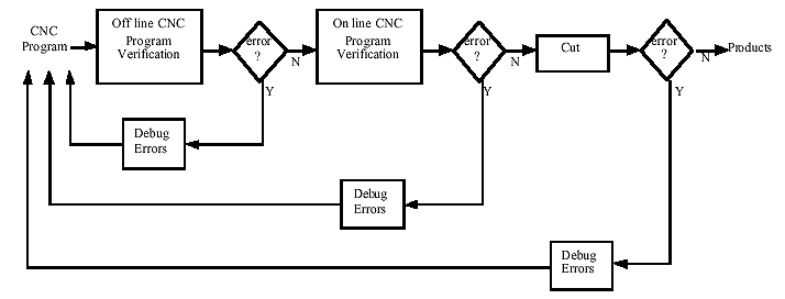
Figure 1. Overview of CNC programming learning activities. Advantages of Developing and Using an In-House Part Program Verification System
A CNC program verification system is a computer software package used to check the correctness of a part program offline before it is executed online. The advantages of using the part program verification system are summarized as follows:
- Suppression of leading/trailing spaces/zeroes, empty lines, and so on. If a student writes an NC block that includes "N20 G01 0X0. 110" as a command, machine-errors will be caused by the mistakes in the underlined section. These mistakes include a leading 0 and an extra space. In-house part programs will detect these errors to correct mistakes so that the block reads: "N20 G01 X0.110". Between 20 and 100 of these blocks are present in typical student programs; errors such as those indicated above are often difficult for students to observe and correct manually. By sensing and correcting these errors automatically, the in-house part program saves students frustration as they learn new skills, thus increasing their learning efficiency.
- More efficient use of in-class time: Class time will be more productive because debugging time is
- Ease and safety of using the part program ( Lynch, 1994 ): The CNC part program is checked by the verification system before it is downloaded into the controller. Using an effective tool, instead of trial and error, on a CNC project allows the movements of the cutter and the workpiece to run smoothly and according to plan. Thus, students will feel comfortable, safe, and confident when working with their programs. Students' attitudes toward learning CNC programming will be more positive and productive.
- Reduction of wasted time and materials: When programs are verified offline, i.e. (not on the CNC machine), the machine can be used for real cuts. Students will enjoy success the first time with only one piece of material needed for each of their projects. Most important, students, instructors, and the machine all benefit from the amount of time and
- Reduction of tool and machine costs: Pre-checked part programs will prevent unexpected damage to tools and machines, thus reducing costs and lag time due to repair.

Figure 2. Block diagram of the CNC machine. Overview of Numerical Control
Over the last few decades, the utilization of computers in manufacturing has been one of the most significant developments in improving the productivity and quality of manufacturing systems ( Singh, 1996 ). Numerical control (NC) was one of the earliest computer applications used to control individual manufacturing functions on the shop floor level. Most CNC machines in use today are metal-cutting machine tools. As shown in Figure 2, CNC machines basically consist of a machine tool and MCU, also known as the machine controller.
CNC machines must be programmed for each different part they produce. The collection of instructions used to produce a part on CNC machines is called a CNC part program. The instructions are entered into the MCU in a serial manner. Then, the MCU interprets these instructions and generates signals to each of the drive units of the machine to accomplish the required action. There are four basic types of input media: keyboard (manual data input), punched tape, magnetic tape, and direct numerical control/distributive numerical control ( Seames, 1990 ).
Structure of the CNC Part Program
Figure 3 shows the bottom-up hierarchy of CNC part program elements. A CNC part program is essentially a string of characters. A character usually requires 8 bits of memory to represent its control value. A bit is the basic unit of memory. The control value of a bit is either 1 (high, on) or 0 (low, off). Characters used in CNC part programs can be classified into three categories:
- Capitals: A - Z
- Digits: 0 - 9
- Special Symbols: (, /, %, etc.)
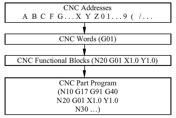
Figure 3. Structure of the CNC part program. Characters are often grouped into words (or commands). Each command directs a specific element of control data (e.g., a machine speed or a tool number). The basic categories of commands are listed as follows:
- Sequence or block number (N, H, or P code): Identifies a block.
- Preparatory function (G): Prepares the MCU to perform specific operations.
- Miscellaneous functions (M): Specify certain miscellaneous or auxiliary functions available on a particular machine tool.
- Dimension words (X, Y, Z, etc.): Specify the coordinate position of the cutting tool.
- Feed words (F): Specify the feed rate of the cutting tool.
- Speed words (S): Specify the spindle speed.
- Tool number (T): Identifies and selects a tool from an automatic tool changer.
Commands that remain active until canceled by another code are called modal commands; rapid traverse and speed commands are examples of modal commands. A nonmodal command is one that is active only in the line in which it is issued, such as the dwell command.
Words can be grouped into blocks (statements). The way in which individual commands are arranged within the block is referred to as the block format ( Singh, 1996 ). The three primary block formats used in the industry are fixed sequential, tab sequential, and word address.
In the fixed sequential format, each block consists of exactly the same number of words entered in a specified order, each word consisting of a fixed number of digits. The tab sequential format is essentially the same as the fixed sequential format, but they differ in that a TAB character precedes each word within a block, except for the first word. In the tab sequential format, the TAB character for a specific word does not need to be followed by a number if the number is not required in that block.
The word address format is used on virtually all modern CNC machines. It is considerably easier to use than the other two formats. A word consists of a letter code followed by associated numeric data. Normally, only the negative sign has to be entered if required. Different words have different numbers of digits. A programmer writing a program should know the format specification for the machine that will run the program. Some machines allow suppression of leading zeros, while others can suppress trailing zeros. Certain machines require that decimal points be entered explicitly as part of the command data. The number of spaces and the number of empty lines allowed in a program also vary from machine to machine.
Blocks are grouped in CNC part programs. The following are the basic methods used to create part programs ( Thyer, 1991 ):
- Manual programming.
- Computer-aided programming (CAP).
- CAD/CAM-based programming.
For some parts, it is easier and faster to manually create a part program directly in word addressed format. On the other hand, the use of computers with part programming languages such as Automatically Programmed Tools (APT) considerably reduces the labor involved in creating part programs for complicated parts. Advances in computer capabilities combined with the fall in the cost of computing have led to the development of more sophisticated computer-aided design (CAD) systems with far better part definition capabilities than APT. Well-developed part definition capabilities of CAD systems have been combined with the machining capabilities of part programming systems in a logical progression. These combined systems are called CAD/CAM systems. Most CAD/CAM systems can directly generate a cutter location file, which can be post processed for use on specific machines.
Developing a CNC Part Program
Table 1 shows a CNC part program written by a student for the Fadal VMC40 CNC machine. The first line of the part program is the BEGIN block, which serves as a program identifier, and the last line is the END block, which will stop all movements of the machine table, spindle, etc. The rest of the part program performs other functions and machine operations. The string, starting with a left parenthesis at the end of each block, is a comment. This program has many errors, which are indicated in bold fonts. The controller of the VMC 40 machine is capable of pointing out some of the errors online; the offline utility of the machine is capable of the same. Some severe errors, however, cannot be detected, e.g., 670 and F500 on line N20, and G0 on line N60. Undetected, these errors could result in unexpected damage and injury. Some CNC machines, especially older machines, do not have these capabilities and the utilities. Therefore, a CNC part program verification system is being developed for CNC machines, particularly for older machines.
Table 1 An Example of a Student's CNC Program with Errors.
N10 01001 (* should be O1001)
N @0 G90 G17 670 S2000 F500. (*N20 and G70)
N30 M6 T112 (* tool #12 T12)
N40 G0 E28 X0. Y0. Z0.5 M3
N50 X0.5 Y0.5
N60 G0 Z-0.1875 (*G01)
N70 X2.5
N80 Y2.5
N90 X0.5
N100 Y0.5
N110 G0 Z0.5
N120 E0 X0. Y0. ZO. (*G28 and Z0.0)
N130 M02Developing and Using a CNC Part Program Verification System
The CNC program has a particular structure that the controller can understand, but it must follow a specific syntax. Writing CNC programs is an error-prone process; debugging a program of any sizable length is usually very tedious. Often, a computer-assisted part programming language can be used to perform tedious and/or complex calculations necessary to prepare the program. However, even with this help, some important commands of a program could still be missing, or the program could be incomplete or incorrect with regard to factors like spindle speed, tool size, fixture offset, depth of cut, feed rate, and tool path. These mistakes could cause damage to the tools and the machine, and injuries to the operator and other people as well. For these reasons, the tool path should be checked for errors before the part program is run on the machine.
As shown in Figure 4, the CNC part program verification system consists of four major components: the character recognition system, word recognition system, fuzzy-nets system (FNS), and the tool path viewer. The tool path viewer is the last to be developed, after the other components have been implemented. The input to the verification system is a CNC part program and the output is a correct CNC part program.
The function of the character recognition system is to separate characters of CNC part programs into tokens such as keywords, word identifiers, special symbols, and constants. If an error is detected, the system will prompt the user to modify the code and recheck it. Otherwise, the tokens are passed to the word recognition system.
The word recognition system is a module that groups the tokens together into block structures. If an error is detected, the system prompts the user to modify the token and recheck it; otherwise, the token is stored into memory for later use.
Figure 5 shows the flow chart of the character recognition system and the word recognition system. The input is "N@0 G90 G17 670". In the character recognition system, the invalid character "@" is detected. It should be a "2." The words "N20", "G90", "G17", and "670" are passed to the word recognition system. The invalid word "670" is detected and the user is prompted to enter the correct word.
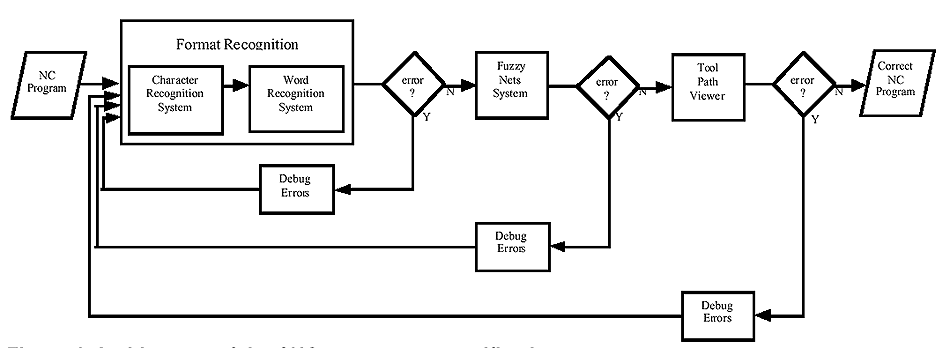
Figure 4. Architecture of the CNC part program verification system. The fuzzy-nets system is an area of artificial intelligence (AI). It is formed by combining artificial neural networks (ANN) and fuzzy logic ( Pal & Srimani, 1996 ). In classical logic, a proposition is either true or false. If a proposition is true, it has a truth-value of true; otherwise, its truth-value is false. Fuzzy logic implies a nonclassical logic with more than two truth-values. Artificial neural network models are composed of many nonlinear computational elements (nodes) operating in parallel and arranged in patterns similar to biological neural networks ( Lippmann, 1987 ). The fuzzy-nets system combines the advantages of the learning capabilities of artificial neural networks and the reasoning capabilities of fuzzy logic.
Figure 6 shows the structure of the FNS. The inputs to the FNS are machining parameters such as speed, feed rate, and depth of cut, and the output is the required cutting power. If the cutting power exceeds tool strength or machine capability, the FNS will prompt the user to modify the values of the parameters. For example, as shown in Table 1, the combination of the words "S2000" and "F500" on line N20 and the word "T12" on line N30 will exceed the strength of the tool. The FNS fuzzifies the inputs, retrieves fuzzy rules from the rule (knowledge) base, defuzzifies the data, and informs the user of the errors.
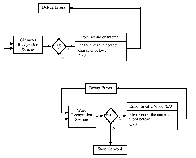
Figure 5. Flow chart of the characters recognition system. In this study, the performance of the fuzzy-nets system was examined for an end milling operation using a Fadal VMC40 CNC machine. The experimental setup is shown in Figure 7. The cutting force signal was measured by a three-component dynamometer mounted on the table of the CNC milling machine with the workpiece mounted on it. The output voltage signal of the charge amplifier was collected by a personal computer with an Omega DAS-1401 high performance analog and digital (A/D) board installed to sample the data online. The data sets were collected to train and test the system.
Implementation
The task of developing a CNC part program verification system is now much easier than before due to advances in (a) integrated development of environments for languages such as C++; (b) object-oriented programming (OOP); (c) powerful graphics software, techniques, and matching hardware; and (d) a variety of CASE (computer-aided software engineering) tools and powerful debuggers to further reduce cycle time ( Prasad, 1992 ).
The CNC part program verification system will be a graphical user interface (GUI) or Windows-based application written in C++ using object-oriented technology. Programming in C++ is very popular because of the wide acceptance of its parent language, C, and its data abstraction and object-oriented features ( Dewhurst & Stark, 1989 ). Object-oriented programming involves three key concepts ( Microsoft, 1993 ):
- Abstraction, which makes writing large programs simpler.
- Encapsulation, which makes changing and maintaining a program easier.
- Class hierarchies, a powerful classification tool that makes programs more user-friendly.
A GUI employs windows, icons, menus, toolbars, boxes, buttons, and other images. It is much easier to use than command-driven and menu-driven user interfaces. Minasi ( 1994 ) noted that a good GUI application should be predictable, attractive, easy to read, customizable, and forgiving. In addition, good GUI applications help to make people more productive.
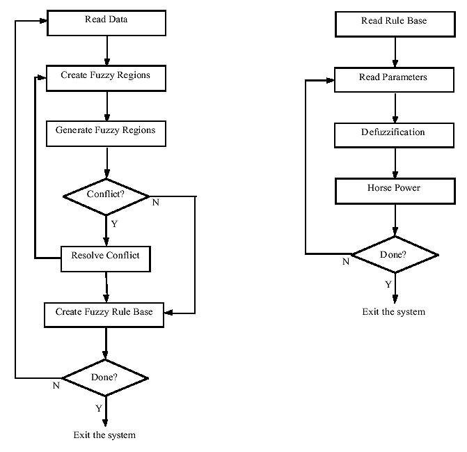
Figure 6. Structure of the fuzzy-nets system: fuzzification and defuzzification. Summary
Financial control is important in industrial technology education. One way to reduce the cost of technical instruction is to prevent damage to equipment and tools. Using general-purpose CAP and CAD/CAM systems for CNC part programming is not satisfactory because they are generally expensive and unsuitable for most applications in the CNC lab. Instead, CAM tools designed for specific processes incorporating special utilities are preferred for writing efficient CNC code.
In this study, a CNC program verification system was developed to check the CNC part program before its execution on a CNC machine. The verification system includes four components: the character recognition system, the word recognition system, the fuzzy-nets system, and the tool path viewer. The system is a GUI application and is written in C++ using object-oriented technology. It is user-friendly and easy to learn in a graphics environment. Developing and using CNC verification systems will enable the participant to be more productive in learning CNC programming; consequently, the verified part program will be more efficient, safer, and easier to manage. The authors believe that the development of this in-house CNC part program verification allows benefits to the CNC laboratory education; proving more effective in both learning and instruction.
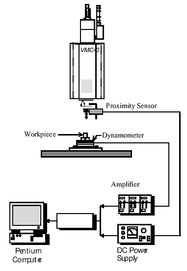
Figure 7. The experimental setup. Joseph C. Chen and Tao C. Chang are both associate professors in the Department of Industrial Education and Technology at Iowa State University. Both are EPT members as well, in the Alpha Xi chapter.
References
Dewhurst , S. C., & Stark, K. T. (1989). Programming in C++ . Englewood Cliffs, NJ: Prentice Hall.
Lippmann , R. P. (1987). An introduction to computing with neural nets. IEEE ASSP Magazine , 4 (2), 420.
Lynch , M. (1993). Computer numerical control advanced techniques . New York: McGraw-Hill.
Lynch , M. (1994). Computer numerical control accessory devices . New York: McGraw-Hill.
Minasi , M. (1994). Secrets of effective GUI design . San Francisco: Sybex.
Pal , S. K., & Srimani, P. K. (1996). Neurocomputing: Motivation, models, and hybridization. Computer , 29 (3), 2427.
Prasad , B. S. V. (1992). Designing programming station software for CNC profile cutting. Computers in Industry , 18 (1), 6776.
Seames , W. S. (1990). Computer numerical control: Concepts and programming . Albany, NY: Delmar.
Singh , N. (1996). Systems approach to computer-integrated design and manufacturing . New York: Wiley.
Thyer , G. E. (1991). Computer numerical control of machine tools . Oxford, Great Britain: Butterworth-Heinemann.


TS