QBARS - v32n4 Building Your Own Mist Controller
Notes On Building Your Own Mist Controller
Frank F. Willingham, Jr., Callaway Gardens, GA
Recently, during a period of unsettled weather, we found it necessary to change the control equipment in our propagation greenhouse. Our mist system had been controlled by a series of clocks and switches allowing for several combinations of misting intervals, but rapidly changing conditions in a single 24-hour period meant new settings very often and we were beginning to see signs of incorrect moisture levels. The obvious solution was a mist controller operating on the evaporation principle. Several such units are available commercially, but in the interest of economy I decided to build the controller described by Warren Berg in the Winter, 1976 (no. 1) issue of the ARS Bulletin. The controller is not difficult to build and actually operates better than most of the commercial units. The following is a brief description of the problems encountered and suggestions for those who want to try this project too.
|
|
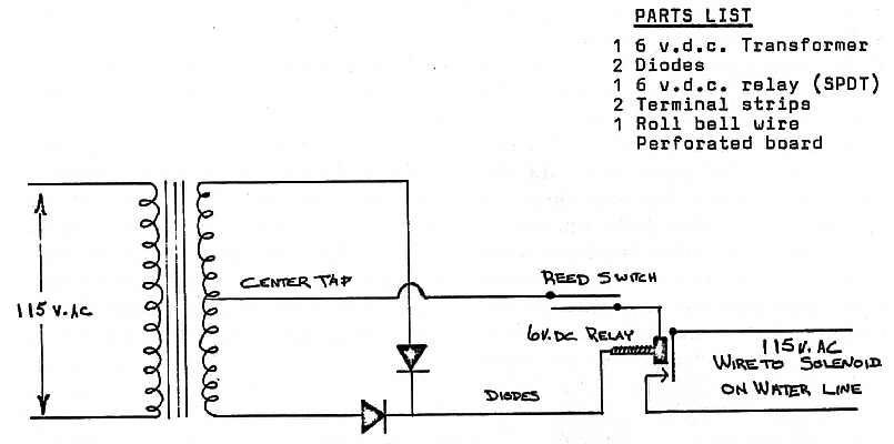
Figure 1. Schematic diagram of rectifier and relay used to
operate reed switch and water line solenoid valve on 115 V. |
1 - For the uninitiated, Plexiglas can be a tricky material to work with, and I recommend practicing cutting and gluing technique before actually beginning the control housing. Straight cuts are a must; I used a jigsaw with a fine-toothed blade. I found it easier to cut out the pieces of the main housing and glue them together than to try and bend a single piece of Plexiglas to the proper shape. Inaccurate cutting can be compensated to some extent by filling in the gaps with any of the clear cements of the "Duco" type. Building the housing was the hardest part of part of the whole project, yet the most important. If it is not square, the mechanism will never balance properly. One final note on gluing: acrylic cement, used to join pieces of Plexiglas, has the consistency of water and runs easily. Hold or scotch-tape pieces to be joined together and apply the cement with a hypodermic needle. The liquid will flow by capillary action between the contacting surfaces and dry quickly.
2 - Stainless steel mesh of approximately 30 meshes/inch is sometimes difficult to find, especially in small quantities. For those in the East or Southeast, you may obtain it from J. M. Tull Metals, Inc., 285 Marietta Highway, N.W., Atlanta, GA. Call first to check the price (404/525-3871).
3 - Radio Shack stores continue to be a good source of parts for the electronics of a controller. Some of the stock numbers originally listed by Mr. Berg in his parts list have now changed or been discontinued, however. Substitutions of similar parts will generally work fine, and I suggest you simply tell the clerk what the part does in the mechanism and let him supply the correct one. I used the largest reed switch available because it is easier to handle.
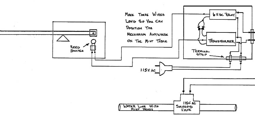
4 - As Mr. Berg notes, the reed switch must operate on low voltage. In our case, we already had 11 5V. solenoid valves installed in the water lines, therefore it was necessary to construct a second relay and rectifier unit to convert 115V. down to 6V. d. c. for the control circuit. Figure 1 illustrates the wiring for this little apparatus, which was mounted on perforated board and mounted in a second homemade Plexiglas box. If you are starting from scratch, it would be simpler to use 24v. solenoid valves in the water lines and use a simple transformer to convert 115V. to 24V. for the entire system. Figure 2 illustrates the complete set-up as we now have it installed. Cost of the project was approximately $20.00 (not including the solenoid valves). The price including a solenoid valve will be about half of what a commercial unit costs, and a lot more fun. The reed switch mechanism provides a very positive on-off action which I actually like better than the commercial units we have tried.
|
|
Figure 2. Pictorial diagram of component wiring for the
complete mist control systems used at Callaway Gardens. |