JOTS v35n2 - Course Modules on Structural Health Monitoring with Smart Materials
Course Modules on Structural Health Monitoring with Smart Materials
Hui-Ru Shih, Wilbur L. Walters, Wei Zheng, and Jessica Everett
Abstract
Structural Health Monitoring (SHM) is an emerging technology that has multiple applications. SHM emerged from the wide field of smart structures, and it also encompasses disciplines such as structural dynamics, materials and structures, nondestructive testing, sensors and actuators, data acquisition, signal processing, and possibly much more. To stimulate students’ desire for pursuing advanced technologies and to ensure that they are well prepared for their future careers, technology educators need to dedicate their efforts to educate the students with this emerging technology. At Jackson State University (JSU), three course modules (Smart Materials and Structures, Data Acquisition Systems, and Lamb Waves Generation & Detection) were added to the existing course to help undergraduate students develop hands-on experience for understanding this technology. The course modules did not require prior knowledge of software and hardware, and they all followed an applied, hands-on approach. These three course modules allowed students to gain insight into the SHM as well as to become knowledgeable users of the instrumentation.
Introduction
Structural Health Monitoring (SHM) is fast becoming a highlight of both research and applications to ensure the safe operation of various structures, such as bridges, ships, pipelines, and aircrafts ( Giurgiutiu, 2008 ; Staszewski, Boller, & Tomlinson, 2004 ). The structure under investigation is energized using actuators. The response to the excitation is sensed at various locations throughout the structure. The response signals are collected and processed. Based on the processed data, the state of the structure is diagnosed.
A successful understanding and application of structural health monitoring depends on an in-depth appreciation of structural modeling, smart materials, signal processing, data acquisition techniques, and more. JSU’s Department of Technology has developed significant teaching capabilities and the experimental facilities for structural control and health monitoring. Three course modules have been developed to introduce structural health monitoring concepts to undergraduates. The field of SHM is vast. These teaching modules are not designed to give an encyclopedic coverage of all the SHM techniques. Instead, the primary objective of these efforts is to provide students with background information and knowledge of principal technologies involved in SHM using smart materials and Lamb waves. Lamb waves are guided elastic waves. Lamb wave techniques have been emerging as one of the most effective methods to detect structural damage.
From these modules, students can learn to use software, hardware, and instrumentation properly both theoretically and in the context of real-world applications. All three modules were offered together for the first time during the spring semester of 2009. Results of these new modules are very encouraging. Being able to see, touch, and interact with entities that demonstrate complex behavior is exciting and appealing to students. Students become very motivated by the diversity and creativity of the course content.
Course Modules Development
Three new course modules (Smart Materials & Structures, Data Acquisition Systems, and Lamb Waves Generation & Detection) were added to the existing Technology course. This addition is intended to present students with a comprehensive view of SHM with smart materials. The new course modules have helped students understand the concept of a smart structural system; it also has helped them to understand its application to performance monitoring of structural systems.
Course Module 1: Smart Materials and Structures
Smart structures utilize active (smart) materials as sensors and actuators to sense and respond to their environment ( Gabbert & Tzou, 2001 ; Srinivasan & McFarland, 2000 ). Smart materials (e.g., electrostrictives, shape memory alloys, and piezoelectrics) are now used in numerous applications. However, most of today’s technology students are not aware of the remarkable properties of smart materials or the applications of smart-structure technology. Therefore, it is desirable to prepare future technologists for the cutting-edge technologies in smart structures, which they will see in broad application during their careers. This proposed course module aims to prepare technologists to meet this demand.
This module demonstrates the properties of piezoelectric materials, and it reveals the basic principles of intelligent structures and structure control. The electromechanical property of piezoelectric materials has both a direct and a converse effect ( Shih, 1999 ). The direct effect is described as the generation of an electric charge in a material when it is subjected to a mechanical stress. The converse effect is described as generation of a mechanical strain in a material in response to an applied electric field. Piezoelectrics are available in polymer (polyvinylidene fluoride or PVDF) or ceramic (lead zirconate titanate or PZT) form. Piezoceramics are stiff and brittle, whereas piezopolymers are compliant and soft. There are two possible ways to utilize piezoelectric materials. First, piezoelectric materials can be used as sensors (direct effect). Second, piezoelectric materials can be used as actuators (converse effect). Because piezoelectric materials are applicable to both sensors and actuators, their use is very popular in smart structures and systems.
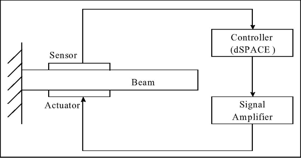
This module consists of lectures and laboratory experiments. The laboratories are developed first; the lectures then support the laboratories. The lectures introduce students to the piezoelectric effects and the fundamental mechanism behind the extraordinary ability for piezoelectric materials to behave as both a sensor and as an actuator. Materials delivered in the lectures also cover the analysis and design of a control system, as well as MatLab, Simulink, and dSpace. The experimental setup is depicted in Figure 1. The test apparatus consists of an aluminum cantilever beam 24.75 inches long, 1.5 inches wide, and 0.075 inch thick. The commercially available PZT patches (QP15W and QP20W from Midé Technology) are used. QP15W works as a sensor and QP20W acts as an actuator. A PZT patch is bonded near the clamped end on each side of the beam. This position was chosen because the greatest strains occur at the fixed end of the beam. The controller is implemented on a dSpace 1104 controller board using MatLab and Simulink software. The Model 7500 power amplifier from Krohn-Hite Instruments is used in the test.
Once the cantilever beam is forced to vibrate, the piezoelectric sensor will continue to generate the signal. When the controller to the actuator patch is on, the sensor signal will be preceded by a control algorithm, and then the control signal will be amplified and fed back to the actuator to suppress the vibration. This cantilevered beam system is a simple form of a smart structure since both the sensor and actuator are integrated parts of the structure. This smart beam has the ability to sense and to respond to vibrations.
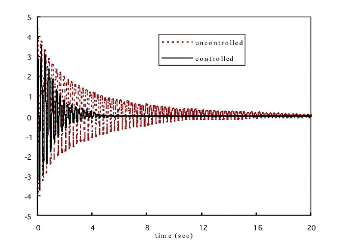
A laser vibrometer (VibroMet 500) is also used to measure the tip displacement and obtain the frequency response of the beam’s vibration. Thus, important parameters of the beam, such as fundamental modal frequencies can be obtained and then used to design the controller. The open-loop response can be validated with analytical results. The dotted line in Figure 2 shows the free vibration of the beam in an open loop after an initial disturbance to its tip. The damping ratio ζ can be determined from the observation of this decay.
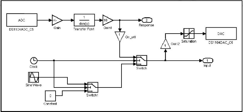
In the next step, a control method is needed to dampen the vibration of the beam ( Song, Qiao, Binienda, & Zou, 2002 ). The proper control method can be chosen with help of computer simulations. Students usually choose the positive position feedback (PPF) algorithm. PPF is applied by sending the structural position coordinate directly to the controller. Next, the product of the controller output and a scalar gain are fed back to the actuator. Students can adjust the gain to optimize the control performance. As mentioned previously, the controller is implemented on a dSpace 1104 controller board using MatLab and Simulink software, illustrated in Figure 3. Simulink is a graphical extension to MatLab for modeling and simulation of systems.
In Figure 3, the block “ADC” which is the analog-to-digital converter, receives the input signals from sensor. The block “DAC” is the digital-to-analog converter. The controller output is sent to the amplifier through DAC. The behavior of a cantilever beam can be represented by a second-order linear transfer function. The fundamental frequency and damping ratio can be obtained from the experiment as previously described. Next, these parameters can yield the transfer function. In Figure 3, the block “Transfer Fcn1” represents the beam’s transfer function.
Flexible structures consist of a large number of highly resonant modes. In general, PPF can offer quick damping for a particular mode. The input value of the PPF controller can be considered as the modal displacement. The resonant frequency of a controller is set to the designated modal frequency of the structure to be controlled. Around the resonant frequency, the phase lag of the controller is about 90 degrees. The output of the controller is the modal velocity feedback signal. Thus, the controller can reduce resonant responses of the structure by increasing the system damping at that modal frequency.
An important issue in designing a controller for a flexible structure is whether the developed closed-loop system will have sufficient robustness to deal with uncertainties in the structure. One more advantage of the PPF algorithm is that the controller can function as a special bandpass filter. Frequencies that are lower or higher than the frequency of the filter will be depressed. Thus, the controller can guarantee closed-loop stability in the presence of uncontrolled modes.
The control performance has been observed in the time domain by monitoring the transient behaviors of the beam. The decaying behaviors are presented in Figure 2 for both the controlled and uncontrolled cases. From this figure, the effectiveness of the present vibration control can be clearly understood.
Smart material systems exhibit very complex coupled physical behavior. From this experiment it can be seen that, in piezoelectrics, the coupling is in between mechanical stresses and electrical potentials. Smart materials and structures are a rapidly growing interdisciplinary technology embracing the fields of materials and structures, sensor and actuator systems, and information processing and control. Study of smart materials can increase the interdisciplinary experiences of the students.
Course Module 2: Data Acquisition Systems
The broad field of SHM encompasses many advanced technologies that, when integrated, provide a system that can potentially identify and characterize the performance and/or possible deterioration of a structural system. For a SHM system, a data acquisition subsystem is required to record a structure’s response to ambient and external loads.
A course module has been developed to allow students to gain a basic knowledge of data acquisition with hands-on experiences. The focus of this module is to give students a starting point for developing the data-acquisition system. In recent years, LabVIEW has been widely used in applications where engineers, scientists, and technologists want to acquire, analyze, and present data. LabVIEW is a graphical programming language developed by National Instruments (NI). LabVIEW is used in this class to write programs for the acquisition, processing, and presentation of data. Thus, the additional benefit is that students are also introduced to programming concepts. The graphical programming environment of LabVIEW has proven to be a suitable teaching mechanism for students to use to learn the basic concepts of loops, case structures, etc. in a short period of time and to generate working programs ( Bishop, 2007 ; King, 2009 ; Strachan, Oldroyd, & Stickland, 2000 ; Sumali, 2002 ; Zhao, 2006 ).
The LabVIEW environment consists of two main windows: the block diagram (Figure 4) and the front panel (Figure 5). The front panel is where the developer can build the user interface through the use of various GUI objects. Students build the front panel with controls and indicators, which are the interactive input and output terminals, respectively. Controls are knobs, push buttons, dials, and other input devices. Indicators are graphs, LEDs, and other displays.
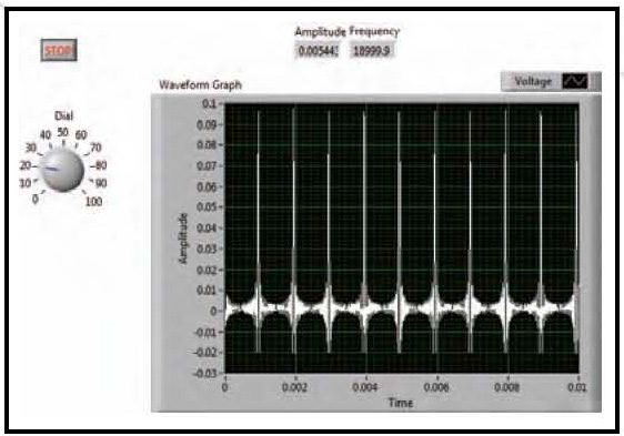
When a front panel item is dropped on the screen, a terminal is also created on the block diagram automatically. The block diagram is where the functionality of the LabVIEW program (known as a virtual instrument or VI) is defined. A wide variety of function blocks (also referred to as VIs) are available to allow the user to define any functionality that they want. In addition, the VIs that allow the user to build his/her program, such as while loops, for loops, and case structures, are also available as in any programming language.
This module is designed so that the knowledge and techniques that are introduced can later be used in further studies and applied in SHM. The module is a mixture of lectures and practical works. In lectures, the basic features of LabVIEW are first covered along with the data-acquisition hardware. The procedures of LabVIEW data flow programming are introduced. The comparison between LabVIEW and the traditional programming languages is presented. The block diagram and front panel for a LabVIEW program are discussed. In addition, the editing features of functions palette and controls palette are introduced. A brief discussion of the hierarchy of the organization of various panels on those palettes is also presented. Due to the limited time available, LabVIEW is not be covered in detail.
In the laboratory sessions, students are instructed to perform the tutorial from the LabVIEW Hands-On Course Manual (2005), the manual that is also used by NI in its training courses. For all of the exercises, the instructor provides common electronic tools and components (e.g., multimeters, oscilloscopes, breadboards, function generators, and data-acquisition systems). A data-acquisition system includes a computer, a LabVIEW, an NI PCI 6251 data-acquisition (DAQ) board, and an NI BNC 2110 connector block. Through these practices, students should gain an understanding of the capabilities and structure of a computer-based data-acquisition system as well as the ability to write simple programs to acquire, process, and store data.
Course Module 3: Lamb Waves Generation and Detection
SHM techniques are being developed to reduce operations and support costs, increase availability, and maintain the safety of various structures, such as bridges and aircraft. Conventional ultrasonic methods, such as pulse-echo techniques, have been used successfully to inspect structural integrity. However, the application of these traditional techniques has been limited to testing relatively simple geometries or inspecting the region in the vicinity of the transducer ( Yang & Qiao, 2005 ). A new ultrasonic methodology which uses Lamb waves to examine the structural components has been developed. Lamb waves are guided elastic waves, which can travel relatively large distances with very little amplitude loss; they offer the advantage of large-area coverage with a minimum of installed sensors ( Giurgiutiu, 2003a ). Thus, in contrast to the conventional methods, the guided-wave technology can be used to inspect the entire structure in a single measurement, and it can also inspect inaccessible regions of complex components. This module is designed to provide students with the foundational knowledge for understanding SHM using Lamb waves.
For Lamb waves, at a given frequency, at least two modes (one symmetric and one antisymmetric) are generated. As frequency increases, the number of simultaneously existing waveforms also increases. Lamb wave propagation is usually highly dispersive. Therefore, how to choose the best frequency is a major issue. In Lamb wave inspection, mostly the S o (symmetric) and A o (anti-symmetric) modes are used. So and A o are referred to as the fundamental modes. These two modes are the most important because they exist at all frequencies, and they carry more energy than the higher order modes in most situations.
So and A o modes are often called the extensional mode and flexural mode, respectively. The A o Lamb mode has a much lower wave speed than the S o Lamb mode, and therefore it has a smaller wavelength, making it more sensitive to smaller levels of damage. However, the symmetric waveform has a substantially greater group velocity and would therefore arrive at a sensor well before the anti-symmetric waveform. Kessler, Spearing, Atalla, Cesnik, & Soutis (2001) recommended use of the A o mode because of lower attenuation. Alternatively, selective excitation of the So mode has also been reported ( Giurgiutiu, 2003b ). At low frequencies, below 1 MHz, only A o and S o Lamb modes are present. Frequency excitation ranges above 1.5 MHz would produce other modes that will make Lamb mode selection more difficult. In order to generate only a few Lamb wave modes, narrowband techniques are necessary. Thus, a frequency range of up to 500 kHz is usually chosen. Giurgiutiu (2005) has also shown that, by adjusting the excitation frequency, it is possible to tune certain transducers to excite a single mode (either S o or A o ) dominantly.
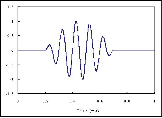
According to four studies ( Giurgiutiu, 2003a ; Hong, Sun, & Kim, 2005 ; Ullate, Saletes, & Espinosa, 2006 ; Yang & Qiao, 2005) , using the tone burst smoothed pulses can improve the feedback signals and enhance the reliability of damage detection. In the experiment, the excited transient signal is made up of a windowed five-cycle sine tone burst (shown in the Figure 6). The center frequency is varied. This signal is windowed in order to get a single wave traveling at the desired driving frequency. Because the pulse has a finite duration, a range of frequencies is excited rather than a single frequency, and dispersion distorts the shape of the pulse as different frequency components travel at different velocities.
Among the various transducers available for damage detection, piezoelectric materials are particularly attractive because they can act simultaneously as transmitters and receivers. These transducers can be bonded or embedded on the structure to be analyzed. Their reduced thickness, low weight, and low cost make them very useful when designing an integrated damage monitoring system (Hong, et al., 2005). In the experiments, piezoelectric transducers (APC-850, 8 mm x 8 mm x 0.3 mm in size) are used to generate and receive the wave.
Students have learned how to operate a function generator and DAQ board, as well as write the LabVIEW program. This module is designed so that it can integrate the knowledge they gained and tools they acquired from the first two modules. The experiment in this module enables students to test their abilities in using a data-acquisition system to acquire data.
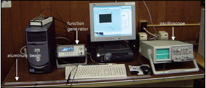
This module is also laboratory intensive. An aluminum beam (or plate) was used in the experimental measurements. Several square piezoceramic elements were bonded on the structure surface at the different positions. One can serve as the actuator to generate the Lamb waves. The others perform as sensors to detect the waves. Figure 7 shows the test setup, which includes an arbitrary function generator, a digital oscilloscope, and a computer. The piezoceramic actuator was excited by a signal constructed and transferred to an arbitrary function generator (Agilent 33220A). This function generator could read the digital signal and output the corresponding analog signal to the actuator. The measured signals were obtained with a digital oscilloscope or recorded in a computer with a LabVIEW program.
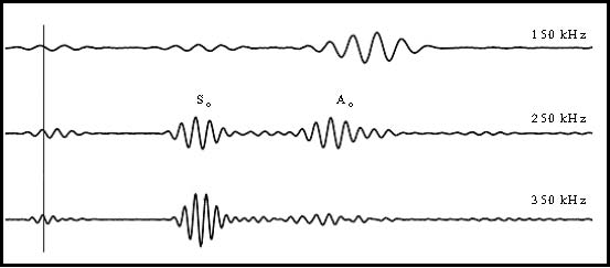
In experiments, both extensional and flexural modes can be excited and detected. Figure 8 shows the wave signals received at the sensor for the 150 kHz, 250 kHz and 350 kHz excitation, respectively. The wave excitation used is a 5-count tone burst. From the first row of wave in Figure 8, it can clearly be seen that A o is dominant at 150 kHz. When the tone burst is tuned to 250 kHz, both So mode and A o mode can be excited. This can be seen from the second row of the wave. At 350 kHz (the third row), S o mode is maximized, whereas A o mode is still slightly excited.
This experiment can show students that the transmission and reception of Lamb waves in thin structures can be effectively implemented using small-size surface-bonded piezoelectric sensors and actuators. The Lamb waves can be used to scan the structures and are capable of detecting internal damage through ultrasonic techniques ( Yang & Qiao, 2005 ). The piezoelectric transducers are inexpensive and unobtrusive. They can be deployed over large structural areas to create active sensor arrays.
The learning exercises described above aim to equip students with the knowledge, skills, and understanding necessary for tackling problems in SHM-related professional fields. The lecture materials cover the core concepts. The laboratory experiments expose students to the hands-on techniques. The three teaching modules presented in this article can easily and seamlessly be integrated to existing technology courses.
Student Feedback
These three course modules were delivered for the first time during the spring 2009 semester. An important outcome of any course is what students think about various aspects of the class. The initial outcome for these modules has been assessed. All students who took the course modules outlined previously were asked whether they thought the structure of the course gave them a good introduction to the basics of smart materials, data acquisition, structural monitoring, and in particular, laboratory and experimental works.
The ratings, relative to a maximum rating of 10.0 on key categories pertaining to the course content, are presented in Table 1. The responses of the evaluation showed highly supportive evidence toward the intended course outcomes. In order to gain additional insight regarding students’ perceptions of the modules, students were also submitted written comments. According to the comments, students increased their perception of the value of technology, and their self-efficacy in performing SHM and DAQ tasks. Although a few students complained about too much time involved with the laboratory assignments, most of the students agreed that the amount of time and work required to complete the assignments was reasonable. The majority of students enjoyed working in the lab. Several students indicated that having additional opportunities to “play with the technology” would greatly enhance their learning. Some students also expressed an interest in being provided with additional information regarding the smart materials themselves, such as where they can be purchased and how much they cost. Overall, most students commented positively about the knowledge they gained. They agreed that these modules were a valuable learning experience.
| Organizes and plans course effectively. | 8.2 |
| I found the course intellectually stimulating. | 8.5 |
| I learned a great deal in this course. | 9.2 |
| Rate overall value of this course. | 8.9 |
The student feedback provides valuable information to the instructors for further improving the modules. Even though student learning and perception were positively affected by the developed teaching materials, there are challenges in future development. Because the laboratory experiments were custom-made, the major challenge is preparing enough experimental systems at a low cost to support a larger student population.
Conclusions
Keeping curricula and lab resources current with respect to the fast pace of technological advances is a challenge. A module-based approach is a new learning paradigm that offers an effective way to address the challenge of emerging technologies. Smart structures and SHM have become increasingly important technologies to ensure the safe operation of various structures. In this work, we advocate a module-based approach for teaching and learning. Three course modules were designed to provide students with a firm grasp of the smart structures and integrated health-monitoring techniques. The modules balance theory and application, classroom lectures and laboratory experiments. These modules also were designed to enable students to gain a competence with tools they can use in their future jobs. These teaching modules have been successfully tested in the three-credit Capstone course offered in the senior year to all the Industrial Technology majors. Extending this learning concept to other practical courses could broaden the students’ practical and advanced skills, which are much desired by industry leaders.
Acknowledgments
The authors would like to thank the National Science Foundation (under grants EEC-0634279 and EEC-0741532) for its support of this project. The authors also wish to acknowledge financial supports from the Institute for Multimodal Transportation. The institute is sponsored by the Department of Transportation – University Transportation Centers Program. The assistantship provided by JSU's Science and Technology Access to Research and Graduate Education (STARGE) Project is also appreciated.
Dr. Hui-Ru Shih is a Professor of Technology at Jackson State University, Mississippi, and is a member of Delta Beta chapter of Epsilon Pi Tau.
Dr. Wilbur L. Walters is an Associate Professor and Interim Chair of the Department of Physics at Jackson State University, Mississippi.
Dr. Wei Zheng is an Assistant Professor of Civil Engineering at Jackson State University, Mississippi.
Miss Jessica Everett currently is an undergraduate technology major at Jackson State University, Mississippi.
References
Bishop, R. H. (2007). LabVIEW 8 (Student edition). Upper Saddle River, NJ: Prentice Hall.
Gabbert, U., & Tzou, H. S. (2001). Smart structures and structronic system . London: Kluwer Academic Publishers.
Giurgiutiu, V. (2003a). Embedded NDE with piezoelectric wafer-active sensors in aerospace applications,
Journal of Materials (JOM-e), Special Issue on NDE, 55
(1),
http://www.tms.org/pubs/journals/JOM/0301/Giurgiutiu/Giurgiutiu-0301.html
.
Giurgiutiu, V. (2003b). Lamb wave generation with piezoelectric wafer active sensors for structural health monitoring. Proceedings of the SPIE's 10th Annual International Symposium on Smart Structures and Materials and 8th Annual International Symposium on NDE for Health Monitoring and Diagnostics , paper # 5056-17.
Giurgiutiu, V. (2005). Tuned Lamb wave excitation and detection with piezoelectric wafer active sensors for structural health monitoring, Journal of Intelligent Material Systems and Structures, 16 (4), 291-305.
Giurgiutiu, V. (2008). Structural health monitoring with piezoelectric wafer active sensors . Boston: Academic Press.
Hong, J. C., Sun, K. H., & Kim, Y. Y. (2005). The matching pursuit approach based on the modulated Gaussian Pulse for efficient guided-wave damage inspection, Journal of Smart materials and Structures , 14, 548-560.
Introduction to LabVIEW 3-Hour Hands-On , (2005). Austin: National Instruments.
Kessler, S. S., Spearing, S. M., Atalla, M. J., Cesnik, C. E. S. & Soutis, C. (2001). Damage detection in composite materials using frequency response methods. Proceedings of the SPIE’s 8th International Symposium on Smart Structures and Materials .
King, R. H. (2009). Introduction to data acquisition with LabVIEW . New York: McGraw Hill.
Shih, H. R. (1999). Damping control of a piezoelectric laminated structure, Journal of Engineering Technology , 16(2), 54-58.
Song, G., Qiao, P. Z., Binienda, W. K. & Zou, G. P. (2002). Active vibration damping of composite beam using smart sensors and actuators, Journal of Aerospace Engineering , 15(3), 97-103.
Srinivasan, A. V., & McFarland, D. M. (2000). Smart structures, analysis and design . Cambridge: Cambridge University Press.
Staszewski, W., Boller, C. & Tomlinson, G. R. (2004). Health monitoring of aerospace structures: Smart sensor technologies and signal processing . New York: John Wiley & Sons.
Strachan, P., Oldroyd, A. & Stickland, M. (2000). “Introducing instrumentation and data acquisition to mechanical engineers using LabVIEW,” International Journal of Engineering Education, 16 (4), 315-326.
Sumali, H. (2002). An instrumentation and data acquisition course at Purdue University, Proceedings of the 2002 ASEE Annual Conference & Exposition , Session 2208. Montréal, Quebec, Canada.
Ullate, Y. G., Saletes, I., & Espinosa, F. M. D. (2006). Lamb waves generation in plates using glued piezoceramics, Boletin de la Sociedad Espanola de Cerámica y Vidrio , 45(3), 188-191.
Yang, M., & Qiao, P. (2005). Modeling and experimental detection of damage in barious materials using the pulse-echo method and piezoelectric sensors/actuators, Journal of Smart Materials and Structures , 14, 1083-1100.
Zhao, J. (2006). Introducing LabVIEW in undergraduate measurements and instrumentation course, Proceedings of the ASEE 2006 Illinois-Indiana and North Central Joint Section Conference , Indiana University Purdue University Fort Wayne (IPFW).